Categories
3D Printer

Elegant solution for a broken PVC pipe

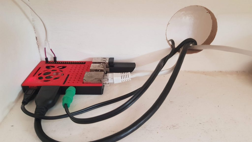
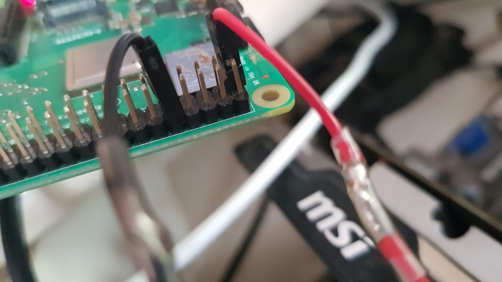
A couple of years ago my dad and I had the crazy idea of running ethernet cables to every building with power on the property. We did this so we can theoretically sit anywhere, and still have a 1gbit/s connection to our NAS at home, and going wire-only until the very last step also helps getting a more stable wifi connection throughout the property.

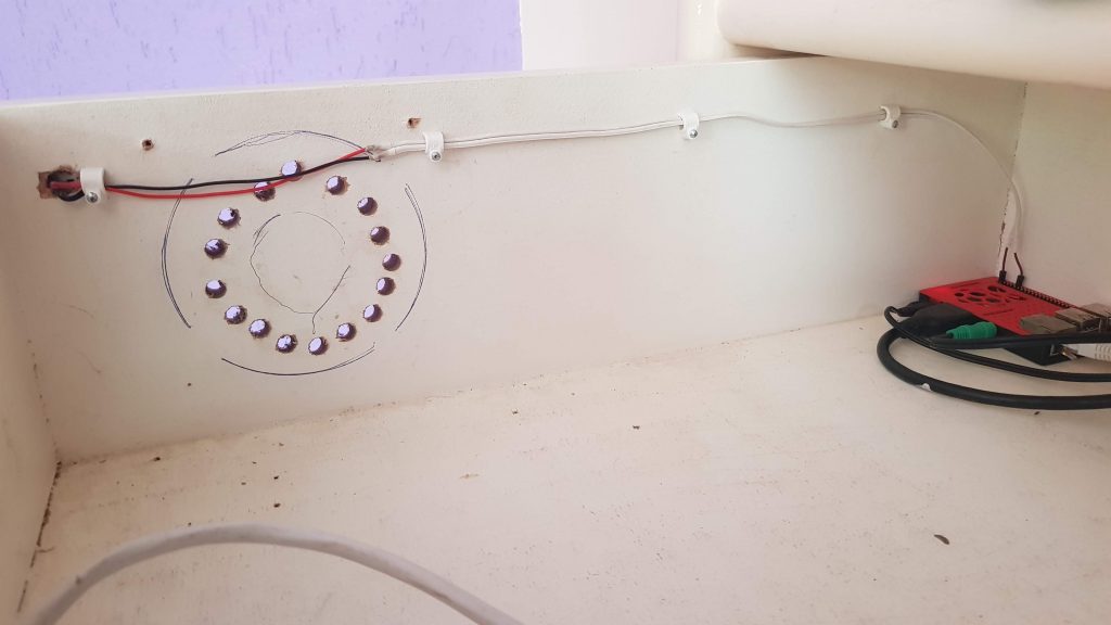
After a couple of years, some mishaps are bound to happen, and our 100m+ ethernet run was no exception. Luckily for us we protected the FTP cat6 cable with a 5/8 (16mm) size PVC pipe, and the piece that broke was only the outer shell and not the cable itself.

The broken PVC pipe, with an ethernet cable inside.

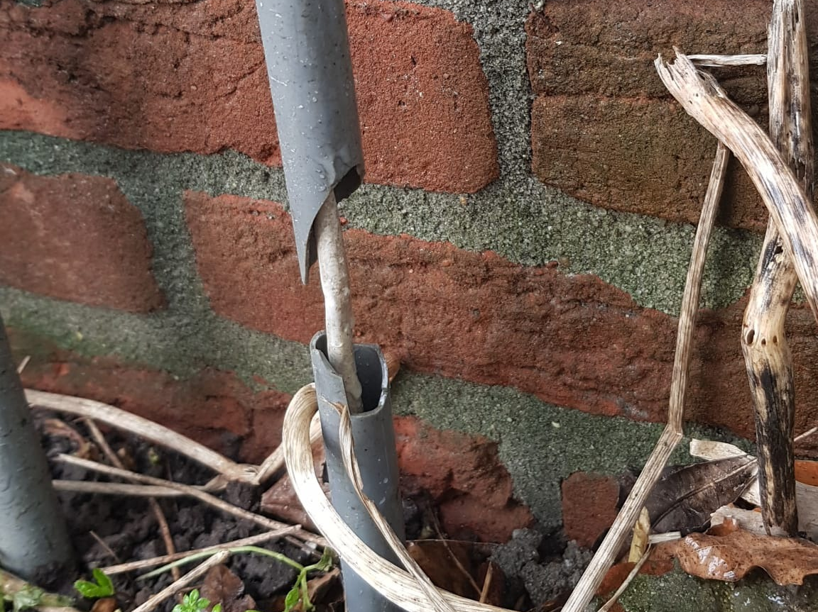
How the pipe got broken so badly is still a mystery to us. We had used an impact resistent PVC pipe, and the pipe is free to move a little bit in the way that we have mounted it, so it must have been a very hard hit. Regardless of how it happened though, we now have an exposed ethernet cable and it needs to be fixed.

Admittedly, about a year has passed since we first saw the broken pipe. There were lots of things to do which were more important, because we didn’t exactly depend on the ethernet cable working, and thus the project was put on hold. We could have put a little electrical tape on it and call it a day of course, but that isn’t a good long-term solution for obvious reasons. Replacing the PVC pipe or ethernet cable also wasn’t an option, because either of them had to be cut/replaced completely. Fast forward to a couple of days ago, where we are now in possession of a 3D printer and I have a little design skills in Solidworks, it was about time to fix it the “good” way.

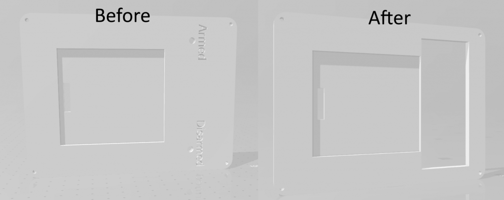
I got my electronic caliper to the pipe and did some measurements for the diameter of the pipe and the length of the broken piece. These turned out to be 16mm and about 90mm respectively. After about 15 minutes of modeling on my laptop, I managed to design something that doesn’t look half bad if I say so myself:

One half of the “pvc patch” I designed.

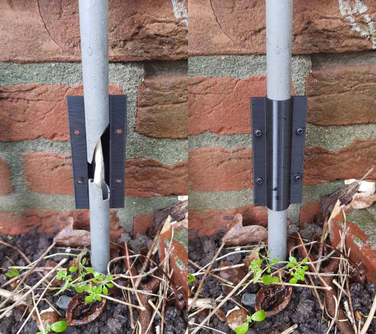
I designed the part around a semi-circle, such that it can be printed twice and will make a perfect circle when mounted using the included screw holes. Now it was just a matter of printing the part two times, and mounting them to the PVC pipe.

The printed piece mounted on the broken pipe.

And that’s it! A broken PVC pipe fixed without cutting either the ethernet cable or the pipe itself, and it can withstand some (more..) abuse again.
If you happen to have found yourself in a similar situation, I have uploaded the Solidworks and STL files to Thingiverse, so you can adjust and/or print the models for yourself: <link t.b.a.>
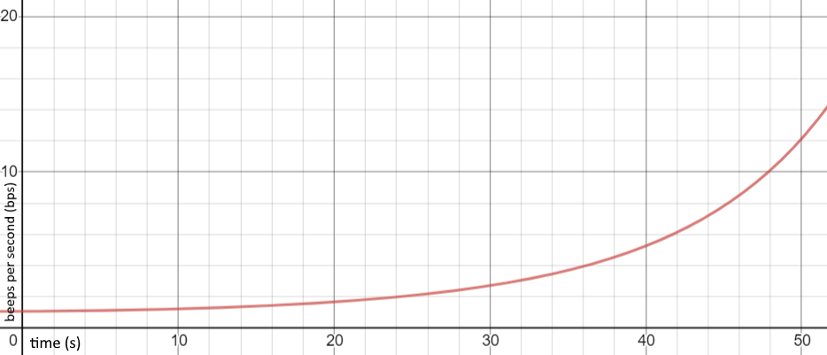
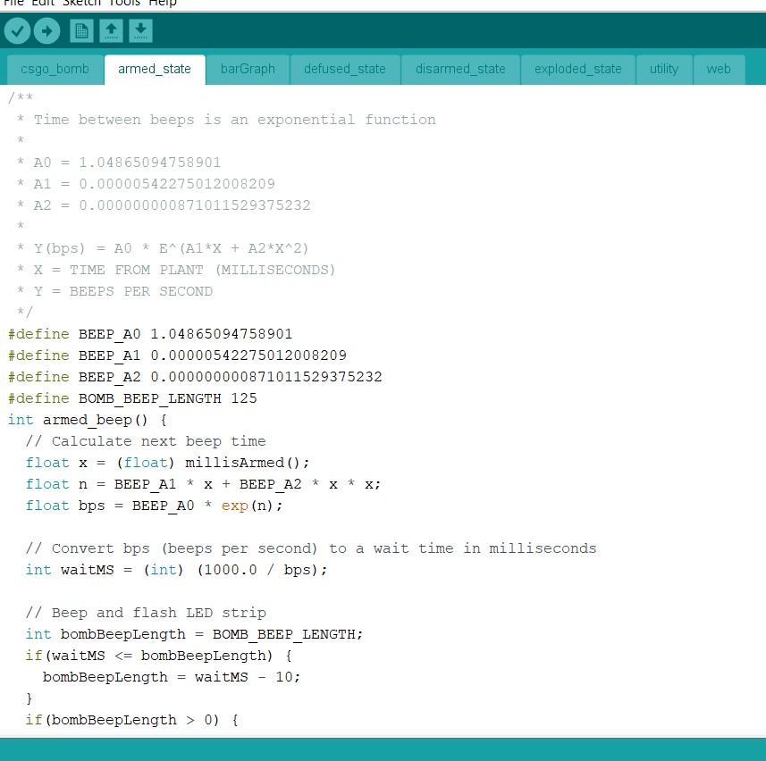
Categories
Bukkit/Spigot stuff Computer/server projects

Speed up the Minecraft plugin development cycle

I developed a tool to help speed up the Bukkit/Spigot plugin development cycle. It’s quick and easy to use, doesn’t require much set up and here’s how to use it!

WatchdogReloader

WatchdogReloader is a simple utility plugin I made, which reloads a plugin when the .jar file gets changed inside the plugins folder. It monitors the folder using a watchdog service.
You can download the plugin here: https://github.com/WouterGritter/WatchdogReloader#download

You just have to install the plugin, make sure the plugin you want to watch is loaded (by typing /reload once) and typing the command /watch <plugin>. It will tell you how to do this in chat as well!

A message generated by WatchdogReloader after a new plugin has been dropped in the plugins folder

FTP-reachable development server

Now that the plugin gets reloaded if the jar file gets changed, it’s time to speed up the process of getting the jar file in the plugins folder of your development server. Whether you host your development server locally or externally, this will work! You just have to make sure that the server files are reachable through FTP. If you host your server externally this is easy enough to do and you probably already have this set up.

If you are hosting your development server locally on Windows, I recommend downloading this program: https://www.sentex.ca/~mwandel/ftpdmin/
It’s old but gold. To use it for our purposes, put the .exe file in the server folder and write a batch file containing the following:

ftpdmin.exe -ha 127.0.0.1 .

This will set the host address (-ha) to 127.0.0.1, so nobody can reach the server outside of our machine. The root folder of the FTP server will be where the .exe file is placed in (.).

The username and password is not checked when a connection is made. You can enter whatever you’d like.

Maven FTP artifact

Now that you’ve got an FTP server running, it’s time to tell maven to upload the assembled .jar file of your plugin to it. It’s actually fairly simple!

Put this inside your pom.xml file, you don’t have to change anything about it:

<build>
    <plugins>
        <plugin>
            <groupId>org.codehaus.mojo</groupId>
            <artifactId>wagon-maven-plugin</artifactId>
            <version>1.0</version>
            <executions>
                <execution>
                    <id>upload-assembly</id>
                    <phase>install</phase>
                    <goals>
                        <goal>upload-single</goal>
                    </goals>
                    <configuration>
                        <serverId>ftp-repository</serverId>
                        <fromFile>${project.build.directory}/${project.build.finalName}.jar</fromFile>
                        <url>${ftpUrl}</url>
                        <toFile>plugins/${project.build.finalName}.jar</toFile>
                    </configuration>
                </execution>
            </executions>
        </plugin>
    </plugins>
</build>

Once that’s done, you need to put this in your global settings.xml file:

    <servers>
        <server>
            <id>ftp-repository</id>
            <username>FTP_USERNAME</username>
            <password>FTP_PASSWORD</password>
        </server>
    </servers>

    <profiles>
        <profile>
            <id>FTP upload</id>
            <activation>
                <activeByDefault>true</activeByDefault>
            </activation>
            <properties>
                <ftpUrl>ftp://FTP_SERVER/</ftpUrl>
            </properties>
        </profile>
    </profiles>

You have to change the FTP_USERNAME, FTP_PASSWORD and FTP_SERVER values to suite your environment.

Testing your plugin

Now that you are done with the installation process, the process of compiling the plugin, uploading/moving the plugin and reloading the server is greatly reduced in time. It’s just a matter of double clicking the install button and everything will be done for you!

Maven install button in IntelliJ
Console output of WatchdogReloader after clicking the install button for a plugin

Categories
Computer/server projects Hardware projects

Zero-fan, GTX 1060 powered Home Theater PC

The idea

We have always had a Home Theater PC (HTPC) in our living room. It was a makeshift computer, being made of old computer parts and a cheap SSD. It worked fine, however there were a few compromises we had to make while using it. The fans were very loud, startup times were slow (even though it had an SSD) and it lacked overall performance. It could be used to stream Netflix or live television, sure, and it could even handle games like rocket league on low settings. But it was still time for an upgrade!

We managed to get our hands on a decent gaming machine. It consists of a GTX 1060 graphics card and an Intel Core i5 processor. Triple A games on medium settings are no problem for this machine. So, two of the three problems are solved: it’s capable of playing games with decent quality and the boot time is a lot faster. It was time to tackle the third problem: the noise..

The execution

I’ve always been a fan of Parsec. It’s a piece of software that lets you stream your entire desktop seamlessly over the internet. It’s aimed mostly at the gaming scene, so you can connect to your powerful gaming tower from a low end device, but it works just fine for general purpose desktop streaming. It supports streaming over the internet, but it works even better when using it in your own (wired) LAN, which adds only one or two frames of latency.
After some digging online, it turns out you can run the Parsec client software on a Raspberry Pi 3! Can you see where I’m going with this?

Luckily I had an old Raspberry Pi laying around in my shed, however it was very rusty. I crossed my fingers and plugged it in to a 5v power supply and a monitor. It turns out a little rust on a Raspberry Pi isn’t enough to kill the little thing!
After reinstalling Raspbian (now known as Raspberry Pi OS) to the SD card and installing Parsec, the software worked flawlessly. Connecting to the host PC did not have any issues at all, and the Pi could handle resolutions of up to 1080p with 60fps without any issues. With both devices wired to our cat 6 equipped local network, there was virtually no input lag.

So the noise problem was tackled! After writing a few scripts to easily start up the Parsec client GUI and to connect to the host automagically, it feels like you’re using a windows machine running directly off of the Pi!
Another benefit of using a Pi is that it can run 24/7 without using any noticeable amount of power. Knowing this I have installed Raspotify: A Spotify Connect client for the Raspberry Pi that Just Worksâ„¢. With this it’s possible to easily stream music to our 18 year old amplifier from any smartphone!

Power savings..

So, the solution is awesome right! Having a computer you can always connect to using a fanless Raspberry Pi? Well, not quite. The PC running Windows consumes about 60 watts when on idle. To solve this, I enabled Wake-on-LAN (WOL) on the Windows PC. With this enabled, sending a special crafted broadcast packet to our network will turn on the PC as if it’s magic. I installed a program called etherwake on the Pi, following this guide. With it I can start the PC remotely with a simple bash script. But you know me: this wasn’t enough.

The drawer the Pi is sitting in used to be the housing of the old Windows PC, and contained a make-shift power button. It’s basically a simple push button wired to the motherboard. The Pi has a lot of GPIO pins that can be used for LEDs and buttons, so this is exactly what I did. It was just as simple as wiring the button to the Pi and writing a quick and dirty Python script to execute a bash script when the button gets pressed.

Lastly I used Windows’ Task Scheduler tool to shutdown the PC every night at 3 AM if it wasn’t turned off already. This prevents accidentally leaving the computer on and still wasting a lot of power.

Categories
3D Printer CS:GO bomb

Wrapping up the CS:GO bomb project

The making of

In the last post about the project I left you off with a picture of the yet to be finished 3D print of the bottom of the case. I’m glad to tell you that the bomb has been finished, and works perfectly!
If you haven’t read the last (and first) post about this project, I highly suggest having a look at the post here.

So: at this point all the parts have been 3D-printed. It was time to see if everything fits in the bottom part of the case! Remember, I designed (or rather: remixed) this model on my own, so there was a great chance that the dimensions would be a bit off. Luckily, everything fit together nicely at the first print. The most critical holes were the defuse-button hole, the XT60-shaped hole and the hole for the battery voltage indicator. The other 2 holes for the wires and the battery strap weren’t really that critical, since it’s fine if there’s a little wiggle room.

Fitting all parts in the bottom of the case for the first time.

As you can see from the picture, I have also soldered the D1 mini board to some perfboard, with lots of connectors on it and once single resistor (which is a pull-up resistor for the defuse button).

Closeups of the perfboard.

The block-terminals are used for power (+5v and ground), data pins (LEDs and beeper) and the button connectors. The male pin-headers are used for the keypad and the LCD screen. The D1 mini board is also installed using female pin-headers, so the board can be removed if needs be.

After hot-gluing the 5v buck converter and the custom-made perfboard in place, it was time to place the buzzer and lots of LEDs on the outside of the bomb. The LEDs are individually addressable WS2812B LEDs, so I can easily control each LED while only using one data wire. In the end I did not add any code to control each LED independently, but I can add this in the future if I want to.

After wiring and gluing the LEDs and beeper to the outside, the bomb was done! Well, the physical side of it at least. The firmware still needed some changes, more on this later.

Photos of the finished product.

Like I said, the firmware still needed some adjustment. I wanted to be able to change the time after which the bomb would explode, and I also wanted to be able to change the defuse time on the fly. I thought about making these changes over the air using my laptop, but I have an LCD and a keypad on the bomb.. Might as well use it! So I made a little menu with which I can change a couple of parameters. These values are stored in the built-in EEPROM of the ESP8266.

And with this, the project is done. With the web server the bomb is hosting, I can write a program on my laptop to keep track of the state of the bomb. This way I can play certain audio files when, for example, the bomb explodes. I could connect my laptop to a big audio installation and a subwoofer, for example, to make it sound like an actual bomb exploded!

Bill of materials (BOM)

A full BOM for the bomb (get it?). I bought almost all parts from Banggood, but I’m sure the parts can also be found on websites like Amazon. I had most parts laying around at home which made it a bit cheaper for me.

Possible revision 2

There are a couple things that I could have done better. If there will ever be a rev. 2 of my bomb design, these are the things I would change:

  • Built-in battery with a charging circuit to allow charging from a USB port. I used a drone battery, battery strap and XT60 connector to save cost because these are things I have laying around at home;
  • Change the loudness of the beeper in the menu, the beeper I got can’t be adjusted in loudness;
  • Use a microcontroller with more pins. I would love to have controlled the LED in the defuse button through the microcontroller as well, but I couldn’t because there are simply not enough pins on the D1 mini board;
  • Make a case design using the real bomb model in the game. I found the model of the in-game bomb here, but my design skills are simply not good enough to make changes to a model this complicated.

Links

Case design: https://www.thingiverse.com/thing:4543891
Arduino code: https://github.com/WouterGritter/CSGO-Bomb

And now..

The project is done! Now I’ll have to start finding something else to make.. However, we can start playing some CS:GO matches in our garden using laser guns!

It was a lot of fun to make a CS:GO bomb simulation in hardware, in real life. I learned a lot, especially how to do more advanced 3D model design. I hope you’ve enjoyed reading these 3 blog posts as much as I did making the bomb!

Categories
CS:GO bomb

How I got the CS:GO bomb beep pattern

The formula

In short, here is the formula for the beep pattern of the CS:GO bomb:

    \[f(t)=1.05\cdot\exp\left(0.0054t+0.000871t^{2}\right)\]

Where f(t) gives the BPS (Beeps Per Second), and t (0 ≤ t ≤ 45) is the time in seconds (the in-game bomb explodes after 45 seconds).

For a more generalized formula:

    \[g(p)=1.049\cdot\exp\left(0.244p+1.764p^{2}\right)\]

Where g(t) gives the BPS (Beeps Per Second), and p (0.0 ≤ p ≤ 1.0) is the percentage of the time that has passed since the bomb has been armed. This is more useful when you don’t want to be stuck using the 45 second explosion time frame.

A plot of time v.s. beeps per second

The length of each beep is fixed at 125ms per beep.
These formulas approximate the beep pattern of CS:GO’s bomb very accurately.

For information about the note(s) of the bomb beeping, I suggest taking a look at this reddit post. Apparently the notes are different depending on if the bomb is planted on bombsite A or B, fascinating stuff!

How I got the formula

The interval between the beeps are very clearly exponential, so I needed to find or generate a matching exponential formula. After some digging online I couldn’t find any
At first I tried estimating the beeps per second from a YouTube video of the bomb sound roughly every 5-10 seconds, and filling this data into an excel table. When I got this data, I tried to let excel guesstimate the (exponential) formula for it. This was without any luck; the beep pattern still seemed a bit off. Looking back at it, it was pretty obvious seeing as I was just loosely guessing the beeps per second of the original sound.

At this time I had the choice to go all-in and find the exact formula or to make do with the relatively bad formula I had figured out. Of course I chose to get the exact formula!

So, it was time to download an mp3 file of the bomb sound of the game. Luckily I found one pretty easily on YouTube, even without any background music. I imported the file into Audacity and started to find the exact beeps per second for some timestamps, roughly 5 seconds apart and 2 seconds apart when the bomb was about to explode. To find the beeps per second, I selected the part between the start of a beep and the start of the beep after that one. Audacity told me the length of the selection in milliseconds which is accurate enough for what I’m trying to do. Dividing 1 by the length of the selection in seconds gave me the bps at that time.

After gathering 17 data points, it was time to figure out an exponential equation that fits the given data. After using a really old-school application called CADRE Regression, it figured out the values for A0, A1 and A2 for a second degree exponential function:

I used these values in my in-real-life CS:GO (fake!) bomb project to match the in-game beep pattern.

Code snippet of the CS:GO bomb project which calculates beep time between beeps. Note that the A1 and A2 values are different because I adjusted the formula to accept time t in milliseconds instead of seconds.

Categories
3D Printer CS:GO bomb

Advanced CS:GO in-real-life bomb

So, my dad has gotten this crazy idea to play an in-real-life match of CS:GO in our backyard, being a fan of the game himself just like me.
But where’s the fun in CS:GO with (laser) guns, even a bomb-site A and B, but no bomb?

Having done some Arduino/ESP projects before, I started the task to make a hardware simulation of the bomb in the game. The bomb needed to fulfill a couple of things:
– A keypad to enter the code to “arm” the bomb.
– A (loud) beeper, just like in the game.
– An LCD to show the status of the bomb.
– Has to be able to communicate with a computer, to indicate the status of the bomb (for future things like a large projector screen, or a large audio installation).
– Lastly, of course: fancy lights!

Being all hyped, I ordered the parts we did not have lying around at home from Banggood and waited for it to arrive. As soon as it arrived I started connecting the parts together and writing some software. I got a basic CS:GO bomb simulator up and running pretty quickly!

Very early stage of the bomb.

I got the LCD connected and running pretty soon afterwards. In the mean time I was printing an enclosure for it all with my (well, actually, my dad’s) Creality3D Ender 3 3D-printer. I found a nice model made by NightfuryGamer on Thingiverse: https://www.thingiverse.com/thing:3085333.
This model contains a hole for the same keypad I am using for my bomb. However, it does not have any hole for an LCD display which I of course wanted to use. I haven’t done any real 3D model designing in the past, so I wasn’t looking forward to designing or editing the enclosure.

The software I had written for the board (in my case: a D1 mini clone, based on an ESP8266 chip) was far from done, so I put the thought of having to do 3D-designing in the back of my mind. In the mean time, it was time to give this bomb it’s own IP address so it can communicate with my laptop wirelessly!

Shortly after this I found myself having a very unique problem I’d never thought I have. Being a CS:GO player for a long time, you develop a good sense for when the bomb is going to explode in the game, based off of the beeps you hear. See, there is no timer in the game that tells you when exactly it’s going to explode. When trying some basic “algorithms” for the time between beeps, everything just felt a bit off. I tried some basic linear functions, even exponential functions, but nothing worked. I needed to get the exact timing. I couldn’t find anything on Google, so I took the task upon me to find the exact mathematical function for the beeps (can you tell I’m a computer/math nerd yet?). More about this on my other blog post. In short: it involved Audacity, a weird program that fits an exponential curve on a data-set and a lot of time. In the end I managed to get it done!

With the software and hardware part being mostly done now, it was time to start thinking about the enclosure again. Like I mentioned before, I have never really touched 3D modeling before, so I wasn’t looking forward to this part. I have access to a full student version of solidworks, so this is what I was going to use. After half an hour and a ton of struggles, I was finally able to remove some existing features in the model of the top-plate of the existing design. Another half an hour later, I was able to make a hole for the LCD screen. Victory!

Five hours of printing later, it fits perfectly!
Now it was time for the next task: changing the design of the bottom part of the enclosure to remove all existing holes, and make a few of my own. Mainly:
– A hole for the defuse button.
– An XT60 shaped hole for the XT60 connector (more on this in a bit).
– Two holes for a battery strap.
– A hole for the battery voltage meter.
– A tiny hole for the wires for all the lights and the beeper.

The bomb will be powered by an FPV drone battery. This is because I own one, and I have a couple of batteries for it. This way it’s a bit cheaper because I didn’t have to buy extra batteries. And there’s another bonus: the final product will look bad-ass with a battery mounted on the side and wires coming out of it! One disadvantage of this is that the batteries do not have any protection circuit on them, and LiPo batteries need to be handled with care. This is why I needed to put a battery voltage meter on the design as well.
My plan is to wire the buzzer and all LEDs with the wires visible and sticking out, to make it look more like the CS:GO bomb.

Anddddd… That’s it! This is my progress on this project so far. The new bottom design should be done printing in about 10 hours. When it’s done I can start assembling the bomb in its final form!

The models I designed/remixed can be found on Thingiverse: https://www.thingiverse.com/thing:4543891

A screenshot of OctoPrint, the software I use to manage the 3D printer. Note that the printed time left is way off for some reason..

Categories
Hardware projects

ESP8266 lamp project

This is an old post from my old blog, posted on the 29th of January 2019!

Some time ago my dad and I made a couple of WiFi controlled lamps, with the help of the ESP8266 micro-controller. It’s a completely DIY project, and I wrote my own software for both the ESP’s, and the control server is running on our linux machine. In total we made three, but I’d really like to make a couple more.

We bought all the parts from Banggood, and for those three controllable lamps we spent about 37 euros in total. This means each unit costs a little bit over 12 euros, which is not too bad in my opinion. Especially because it has a sweet see through plastic cover on the front, so you can see each little LED blinking away.

Full parts list:

The first step of the project was prototyping. After hot gluing all parts together it looked something like this:

And after nervously connecting mains power to it, it worked without any sparks!

At this stage the relay could be controlled by the website front-end I had developed and tested beforehand.
Now it was a matter of putting everything in a small plastic and waterproof box, and making 2 more of them.
Of course I found better ways of making and connecting everything as I went.

All together in the box it looked like this:

And screwed in place:

For “safety” reasons we added an ordinary switch in series with the live wire going to the esp, and through the esp to the lamp. We did this because if anything went wrong we could just switch off power to the thing.
One side-effect from adding the switch in series is being able to switch off the lamp when you’re there without a phone. Because when the esp starts up it defaults in the off state, you can power-cycle the esp to switch off the lamp. Maybe it would’ve been nice to also be able to switch the lamp on using this method, but it would probably need some extra hardware, such as a capacitor and a resistor to remember the state of the lamp for the couple of seconds the esp didn’t have power.